Hi Ari,
It depends on your purpose.
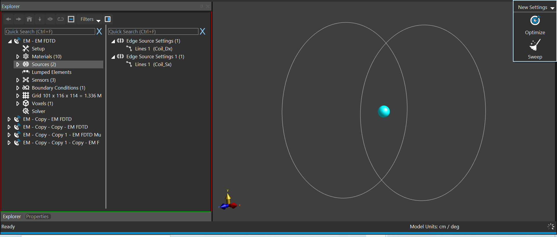
If you use single port simulation, then, you cannot later change the phase difference between the coils. However, if you use multiport simulation, Sim4Life runs 2 simulations for each coil and stores the results separately. This is useful if you would like to postprocess results for different source parameters. For example, you may change the current amplitudes for each coil, or add phase differences. You do not have to run the simulations again. New results will be directly calculated by using the previously stored multiport results.
So, if you have enough memory and would like to try different settings for the sources, you had better to use multiport simulation for the above setup.
If you want to save time and memory and fixed the source settings, then you may chose single port simulation.
I hope this helps.
Sayim