Skip to content

Simulations & Solvers

269 Topics 801 Posts

FDTD, Low-Frequency, Neuron, Mode-Matching, Flow, Acoustics, etc...

Subcategories


  • FDTD, Low-Frequency, Neuron, Mode-Matching, Flow, Acoustics, etc...

    16 39
    16 Topics
    39 Posts
    G
    Hi, I'm trying to simulate a synapse between two identical neuron models, imported from the same .hoc file. I set the simulation as follow (see screenshot): -both neuron have the same HOC Model Settings -The first neuron "L23_PC_cADpyr229_1", pre-synaptic, has an IClamp on its soma -The second neuron "L23_PC-cADpyr229_2", post-synaptic, has a Exp2Syn point process on dendrite 9 -The network connection was created drag & dropping the first neuron's model and the Exp2Syn point process of the second neuron in the network connection settings [image: 1778756649765-f7472fbe-2fe9-4244-9297-34d7a1f29c16-image.png] If I try to run the simulation I get the error messages: Simulation : [Error] Failed to create neuron group ids. Error : Failed to write the input file Error : Unable to start simulation: failed to write input files. How can I solve this error? I already tried using different neurons from different .hoc files. Thank you in advance
  • Simulations fail when multiple simulations are submitted

    Pinned
    2
    1 Votes
    2 Posts
    3k Views
    H
    By default, Sim4Life tries to use all available resources to start as many simulations as you submit or have cores or GPUs available. The first simulation usually starts fine, and the rest fail due to insufficient licenses. You have the option to limit the number of simultaneous simulations in the ARES tool. Please change the Resource Management Option from Concurrent Jobs to One Job at a time as in the attached screenshot. [image: 1569997460703-ares3.jpg]
  • what's the difference between red lines and white lines in gridding?

    Pinned Moved
    3
    0 Votes
    3 Posts
    3k Views
    S
    Thank you for the great explanation.
  • Electrode appears hollow after voxelisation

    3
    2
    1 Votes
    3 Posts
    164 Views
    V
    thanks a lot for the clarification
  • How to Cut a Grid Evenly

    2
    0 Votes
    2 Posts
    36 Views
    B
    To make a uniform grid, you can add all of your simulation objects to a 'Manual' grid settings folder, and then set the 'Priority' of that folder to 0. This will ensure that no grid 'baselines' are placed. Please refer to this forum post for more information about grids.
  • Yoon-sun Arm Stimulation Neuron Tutorial Project Compatibility Issue

    Unsolved
    4
    1
    0 Votes
    4 Posts
    2k Views
    C
    When you mention you are experiencing the same issue, do you mean that you are getting the same error message? Are you getting any license-related errors? Did you install the NEURON solver in the new server?
  • 1 Votes
    2 Posts
    33 Views
    C
    Dear Jihan, The issue you are describing is related to the available screen space, which is too limited for Sim4Life. This can happen when Windows display scaling is above 100% or when the laptop screen has insufficient vertical resolution. Please check the display scaling setting and try 100%; if it is already at 100%, a higher-resolution external monitor may be needed. In any case, a solution is to right-click on the simulation tab and select "New" there to create your simulation. I hope this helps.
  • How to Cut a Grid with Uniform Spacing

    1
    0 Votes
    1 Posts
    15 Views
    No one has replied
  • Adding electrodes to the Grid changes simulation results

    2
    0 Votes
    2 Posts
    687 Views
    C
    Hello, When you only use a single manual grid (0.7 mm) on the bounding box, the entire domain - including the electrodes - is discretized uniformly at that resolution. While 0.7 mm is reasonably fine, it may still be too coarse to accurately capture the very steep electric field gradients near the electrodes, especially for TI setups where interference patterns are sensitive to local field accuracy. When you enable Automatic Grid settings for the electrodes, the solver applies local mesh refinement around those electrode regions. This typically results in a smaller minimum step size near the electrodes than your global 0.7 mm grid. That improved resolution leads to more accurate current density and E-field calculations at the source, which then propagates into differences in the resulting interfering field. So the change you see is not an error - it’s actually a sign that the solution is sensitive to mesh resolution near the electrodes, which is expected. Regarding your other question: Using a bounding box vs. explicitly listing all head tissues generally does not change the result if the grid settings are identical, because the box already encloses all tissues. It’s mostly a workflow/simplicity choice. I hope this information helps.
  • Thermal simulation for temporal interference stimulation

    thermal tis
    1
    0 Votes
    1 Posts
    392 Views
    No one has replied
  • Using multiple sources in Neuron Simulation

    Unsolved
    2
    1
    0 Votes
    2 Posts
    907 Views
    C
    When you provide multiple EM-LF simulations as sources to the Neuron solver, the neuron effectively receives the sum of the extracellular fields/potentials generated by the individual simulations (assuming the same modulation pulse is used). This is expected behavior because EM-LF simulations are linear, and therefore their solutions can be superimposed. To verify this behavior, you can use the Field Combiner tool in Sim4Life: First, combine the EM-LF results using the Field Combiner, which applies linear superposition of the fields. Then, use the combined field as a single source for the Neuron simulation. If you compare this setup to a Neuron simulation where the individual EM-LF results are used as separate sources (with the same modulation pulse), the neuron response will be identical. This confirms that, internally, the Neuron solver is operating on the sum of the fields from the different EM-LF simulations. If additional verification is desired, the EM-LF fields can also be interpolated along the neuron spline (for each simulation individually and for the Field Combiner result) to explicitly confirm that the combined field corresponds to the pointwise sum of the individual fields. Note: the field combiner expects the fields to be at the same frequency. If you would like more information about a specific application, or if you would like to share your project with us to receive more targeted feedback, please do not hesitate to contact us at s4l-support@zmt.swiss.
  • 0 Votes
    3 Posts
    977 Views
    S
    Thanks for the suggestion. I will contact the licensing team at s4l-license@zmt.swiss with the relevant details and will update this thread once I receive their guidance.
  • Temporal interface- SAM head- Low frequency solver

    5
    2
    0 Votes
    5 Posts
    1k Views
    S
    @halder Thanks do much, the call was really very useful.
  • Question about setting up sources in acoustic simulations

    2
    0 Votes
    2 Posts
    953 Views
    H
    Hi @Kihyun, To create an acoustic simulation, click on “Sources”, then change the excitation signal from “Sinusoidal” to “User Defined.” This will provide an “Expression” field that you can edit as needed. I also recommend checking the Acoustic Tutorial in Section 3.7 of the Sim4Life Manual, which you can access from the top ribbon under “Help.” [image: 1761036820889-sim4life_jvkul06rui.png] [image: 1761036826795-sim4life_q3dc6omg4u.png]
  • How to sense values on head.

    3
    1 Votes
    3 Posts
    1k Views
    R
    Solved it - Model the electrode as PEC and use the voltage reader
  • This topic is deleted!

    1
    0 Votes
    1 Posts
    13 Views
    No one has replied
  • 0 Votes
    9 Posts
    6k Views
    M
    Hi everyone, I'm using Sim4Life and currently working with the Optimizer tool. I would like to run the optimization algorithm on a network server using ARES instead of executing it on my local machine. However, I can't seem to find an option in the simulation settings that allows me to select the server as the execution target — the optimizer always defaults to running locally. Is it now possible to run parameter sweeps and optimization tasks on a remote machine in the network (without using a remote desktop session)? If so, how can I configure this in Sim4Life? Thanks in advance!
  • 0 Votes
    5 Posts
    2k Views
    G
    Dear, @AntoninoMC Thank you very much for your detailed clarification. I now understand the fundamental difference between the Ohmic solver and the QS solver, and I have also tried some test runs with the QS solver, which helped me to grasp the impact of frequency dependence more clearly. In my current application, I am applying a voltage to the human body and measuring the potential difference between two points on the head. I am particularly interested in how the measured potential difference changes with the frequency of the applied current. The frequency range I am considering is typically from about 10 kHz up to 100 kHz, but I am also exploring much lower frequencies, down to around 100 Hz. If you could kindly point me to relevant references or scientific literature that discuss similar applications or provide guidance on which dielectric properties are most suitable in this frequency range, it would be extremely helpful. Thank you again for your support.
  • 0 Votes
    1 Posts
    882 Views
    No one has replied
  • Jobs suddenly remain queued indefinitely ... another story

    2
    0 Votes
    2 Posts
    1k Views
    B
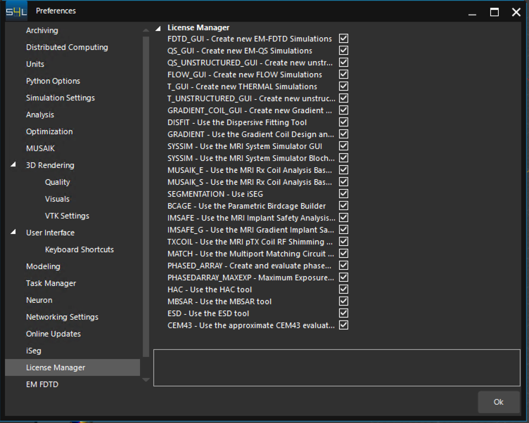
    If simulations are queued indefinitely, this could be an indication of a license issue. To run a simulation, the solver needs to 'check out' a license feature from the license server. When it completes, it marks that license feature as available again. Sometimes, if the application were to crash for some reason, the license feature is not correctly marked as available, preventing other simulations from proceeding because they think the feature isn't currently available to checkout. To resolve this, one thing to try would be to stop and restart license software, or to reinstall the license to ensure that all license features are reset.
  • 0 Votes
    2 Posts
    1k Views
    B
    After creating the voxels for a simulation, the input file can be created without submitting the simulation by right-clicking on 'Solver' in the simulation configuration and selecting 'Write Input File'.