Different frequencies in electrodes
-
Hello dstoupis,
I believe you aim to model the so-called temporal interference. The is a tool in Sim4Life for this called Max Modulation. You need two simulation with the same grid. Then you can multi-select the two fields in the Output View (each from one simulation) to have the Max Modulation button appear in the Ribbon.
Best,
Habib@Habib said in Different frequencies in electrodes:
Hello dstoupis,
I believe you aim to model the so-called temporal interference. The is a tool in Sim4Life for this called Max Modulation. You need two simulation with the same grid. Then you can multi-select the two fields in the Output View (each from one simulation) to have the Max Modulation button appear in the Ribbon.
Best,
HabibThank you @Habib!
It was a simple selection of the two "Overall Fields" to have the "Max Modulation" tool show up! It helps a lot, since extracting the data and the processing it using Python to superimpose the fields and get the corresponding graphs, takes a lot of time.For future reference:
- Create two LF Electro Quasi-Static simulations one with the first desired frequency and another with the second desired frequency
- Use the same grid for the simulations (Grid point count must be the same)
- Run the simulations and extract the sensors
- Select the extracted sensors and magically the Max Modulation tool will appear
-
@Habib said in Different frequencies in electrodes:
Hello dstoupis,
I believe you aim to model the so-called temporal interference. The is a tool in Sim4Life for this called Max Modulation. You need two simulation with the same grid. Then you can multi-select the two fields in the Output View (each from one simulation) to have the Max Modulation button appear in the Ribbon.
Best,
HabibThank you @Habib!
It was a simple selection of the two "Overall Fields" to have the "Max Modulation" tool show up! It helps a lot, since extracting the data and the processing it using Python to superimpose the fields and get the corresponding graphs, takes a lot of time.For future reference:
- Create two LF Electro Quasi-Static simulations one with the first desired frequency and another with the second desired frequency
- Use the same grid for the simulations (Grid point count must be the same)
- Run the simulations and extract the sensors
- Select the extracted sensors and magically the Max Modulation tool will appear
-
@dstoupis
also ,I have some questions when I perform the TDCS, when the max modulation appears, then what should I do to perform the next process? hope I can get your reply. -
@hitina
Please explain what you mean. Have you performed the tDCS analysis and generated the temporal interference field?@dstoupis Thanks for your reply.I have not generated the TI field.
I have some confused questions. I choose the LF-electro Quasi- static as the solver. I want to know how can I set up the boundary conditons .!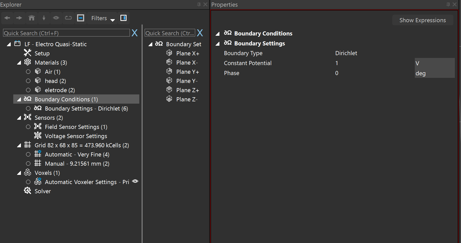 what's more,as the picture shows,how to set up the the current and the voltage of the eletrode.
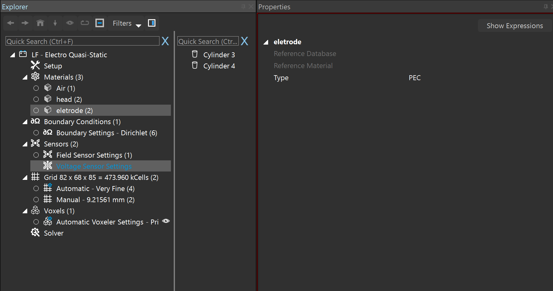
I am learning the performance of transcranial temporal interference stimulation in this days.
hope your reply.
best wishes. -
@hitina
Please explain what you mean. Have you performed the tDCS analysis and generated the temporal interference field? -
@hitina
Please explain what you mean. Have you performed the tDCS analysis and generated the temporal interference field? -
This post is deleted!
-
Hello dstoupis,
I believe you aim to model the so-called temporal interference. The is a tool in Sim4Life for this called Max Modulation. You need two simulation with the same grid. Then you can multi-select the two fields in the Output View (each from one simulation) to have the Max Modulation button appear in the Ribbon.
Best,
Habib@habib hello
i am performing TI simulation with sim4life and after using the max modulation to see the interference between the two field. I have electric field spreading all arround the mesh not only in the brain but in different part or the model (MIDA fULL aNISOTROPY MODEL).
And if i want to know which configuration of the electrode is better for TI simulation, should i compare the amount of electric field that reach the targeted region( for example in the hippocampus)? -
@habib hello
i am performing TI simulation with sim4life and after using the max modulation to see the interference between the two field. I have electric field spreading all arround the mesh not only in the brain but in different part or the model (MIDA fULL aNISOTROPY MODEL).
And if i want to know which configuration of the electrode is better for TI simulation, should i compare the amount of electric field that reach the targeted region( for example in the hippocampus)?
Hello! It looks like you're interested in this conversation, but you don't have an account yet.
Getting fed up of having to scroll through the same posts each visit? When you register for an account, you'll always come back to exactly where you were before, and choose to be notified of new replies (either via email, or push notification). You'll also be able to save bookmarks and upvote posts to show your appreciation to other community members.
With your input, this post could be even better 💗
Register Login